CHALLENGE:
- Generic CAD tool in use was overly complicated for the specific modeling problem, and it required a specialized engineer
- The CAD software was not intended for CFD, so models generated were not suited for meshing for the CFD solver
- Iteration between mixing expert and design engineer was both inefficient and introducing inconsistencies
SOLUTION:
- Develop a GUI application for the mixing expert to represent tank and impeller designs for simulation
- Enable templates to be built to accommodate varying levels of mixing engineer expertise and tank/impeller design
- Have a single application used by engineers and mixing experts with common and individual workflows
RESULT:
- Mixing experts now drive the engineering and design process in a fit for purpose software
- Weeks have been removed from the workflow of Iteration between mixing expert and design engineer
A time consuming and tedious process for running virtual mixing experiments
A significant part of Proctor and Gamble’s (P&G) manufacturing involves mixing fluids. P&G spends resources to design mixing systems that optimize this process. Manufacturing enough new tanks and impellers to physically experiment with all of the design parameters is much too expensive, so CAD models of the mixing tanks and impellers are passed to computational fluid dynamics (CFD) solvers to run virtual mixing experiments. However, this process can still be tedious and time-wasting.
They used a generic CAD tool to build the tank and impeller models, which caused two problems. First, the generic CAD tool was complicated and required a separate trained engineer to build the models rather than the mixing expert. This engineer is, of course, overbooked so a round-trip time of a week between specifying the parameters of a model and getting the model back was not unheard of. If the engineer made a mistake, this process needed to be repeated. Second, this tool was not intended for CFD work, so the models it generates are often not suitable for meshing for the CFD solver.
The workflow was mostly manual: the mixing expert chooses his mixing parameters, gets a model built for him, runs the mesher on the model, builds parameter files for the CFD solver, submits the CFD job to their cluster’s job queue, then collects the solution files and runs the post-processing programs to visualize the results.
Empowering the scientists to build their own experiments
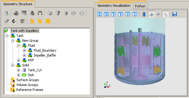
We constructed a GUI application in order to let the mixing expert drive the entire cycle of mixing simulation. We built a library for doing 3D CAD by building up models through combinations of relatively simple primitives. While this is not as powerful as a generic CAD tool for all purposes, it can represent mixing tank and impeller designs well. More importantly, it gives a simple way for mixing experts, who are not CAD experts, to build up their models.
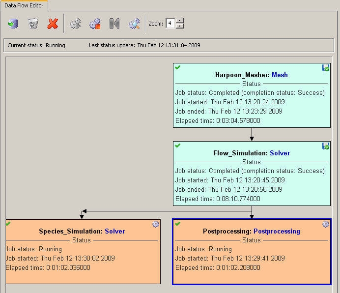
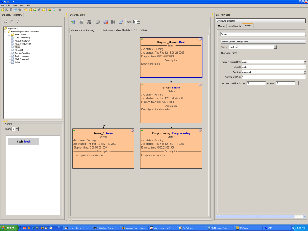
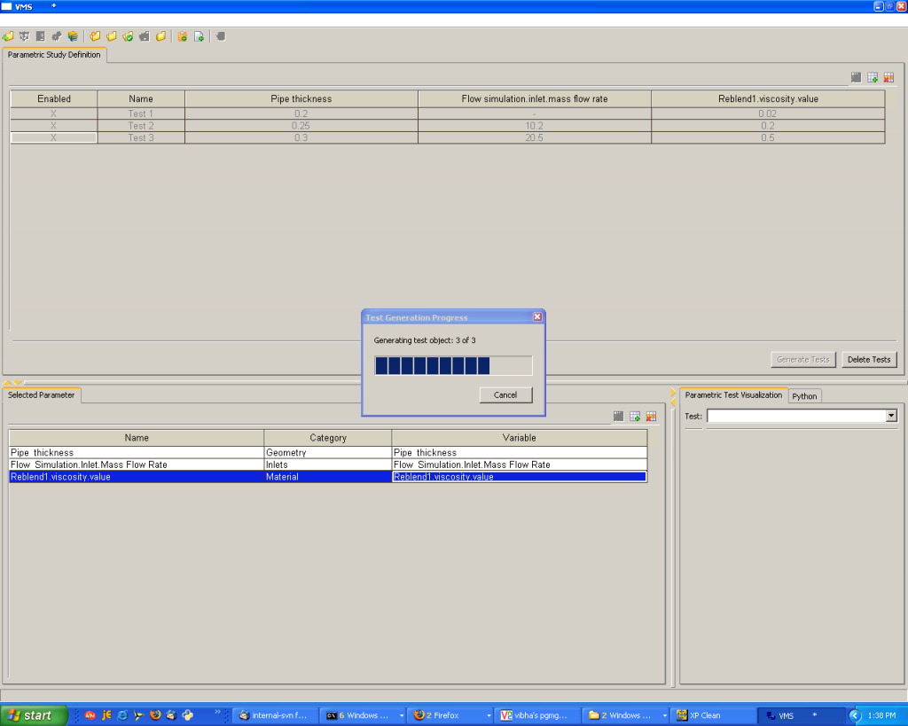
The more sophisticated experts can build templates that represent common classes of tank and impeller designs. A less sophisticated user can use these templates and simply adjust parameters of the templated design. The templates are shared in a common repository accessible over the network. Virtual Mixing System (VMS) lets users construct a series of experiments with a variety of parameters. These parameters may affect the model template, but also CFD solver parameters like temperature and impeller speed. VMS uses these other parameters to generate the appropriate control files for the mesher and the solver according to a customizable workflow. VMS interacts with their cluster’s job queue for the mesher and the solver, but drives the workflow itself.
Want to learn more about what we can help you achieve? Contact Us.
Sample Elements
Seeing the current status of the dataflow
Constructing a dataflow
Viewing the generated parametric geometry
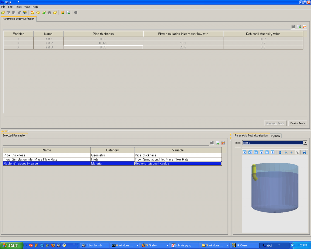
Generating a parametric study
Tank geometry